General: Connecting Wired Inputs
Wired Inputs consist of wired sensors or wired signals from other devices. They are wired to Analog Input (AI), Digital Input (DI), or Universal Input (UI) terminals of controllers that support wired Input points.
Wired Inputs are grouped into 2 main groups:
- Digital - Only 2 possible states: either an open circuit or a closed circuit. Includes: simple switches/buttons, relays, and other types of dry contact (ex. status signals from other devices).
- Analog - Many possible states based on Voltage, Resistance, or Current. Includes: Temperature, Humidity, Pressure, CO2, Position Feedback, etc...
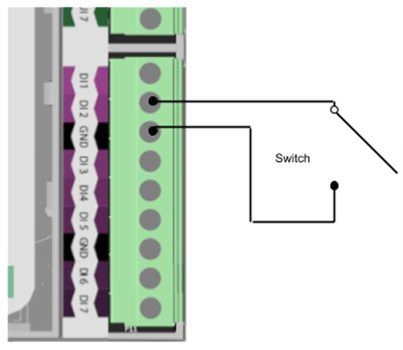
Digital Inputs
Digital Inputs are connected between the Ground(GND) terminal and the selected DI or UI terminal. There is no polarity for Digital Input wiring (ie. input wires can be swapped).
Wiring Diagram:
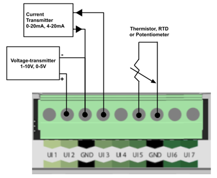
Analog Inputs
Analog Inputs are connected between the Ground(GND) terminal and the selected AI or UI terminal. There is usually a correct polarity for Analog Inputs (ie. correct wire must be on AI/UI terminal).
There are 3 main types of Analog Inputs:
- Resistance - Input is based on resistance. The most commonly used resistance input is Thermistor temperature sensors where resistance varies with change in temperature. There is no polarity for Resistance inputs (ie. input wires can be swapped).
- 0-10vdc - Input is based on DC voltage signal over the range of 0v to 10v. This voltage range is related to a defined range on the device that produces the 0-10v signal.
- 4-20mA - Input is based on current signal over the range of 4mA to 20mA. This current range is related to a defined range on the device that produces the 4-20mA signal. Because this signal is based on loop current it does not suffer from voltage loss due to long wire runs, or damage to the wire.
Wiring Diagram:

Note: On many devices there are input pin configuration settings (hardware and/or software) that must be configured correctly for each different type of input. See hardware specific instructions for these input pin configurations.
Related Articles
Related Articles
General: Connecting Wired Outputs
Wired outputs consist of wired output signals to be sent to other devices. They from the Digital Output (DO), Universal Output (UO), and Relay Output (R1, R2,etc.) terminals of controllers that support wired output points. Wired Outputs are grouped ...Edge iO 28: Connecting Wired Input and Output Points
Edge28 Input/Output Summary Point Type Number Available Details DI 7 Dry Contact / Switch (Open/Closed Circuit) UI 7 Analog: Resistance, Thermistor, 0-10vdc, 4-20mA OR Digital: Dry Contact / Switch (Open/Closed Circuit) DO 5 Digital 0v or 12vdc ...Edge iO 28: Power Requirements and Wiring
Power Supply Requirements Supply Voltage 24v AC/DC Current Requirement 700 mA Minimum Transformer Size 17 VA Power Supply Wiring The Edge28 can be powered by 24 volts AC or DC. The 0v wire from the power supply should be connected to the ...Rubix iO: Modbus RS485 Wiring
Nube-iO Rubix IO Modules are a pure Modbus device; All communications with the IO Modules are via Modbus. This article will detail the correct wiring for the Modbus RS485 Network. To communicate via Modbus the Rubix IO Module must also have its ...Rubix Compute: Power Requirements and Wiring
Warning: Power requirements are different for older models of Rubix Compute. To determine the device version of Rubix Compute, see: Rubix Compute: Identifying Hardware Version If Rubix Compute hardware is Version 0.8 or below, DO NOT FOLLOW the ...